5.
Assessment Module
The Assessment module combines the Quiz questions with the students and
classes. This module contains the
scanner module and interprets the barcodes for the automatic marking of the
assessment paper. Users can also
manually mark non MCQ/MR questions and generate the report. The Marking and Report modules are described
in the subsequent Chapters.
Figure 5.1 shows the main dialog box of the Assessment Module. The left hand side of Figure 5.1 manages the
directories or folders to organize the assessments. Users can create, delete or rename directories
with the respective buttons. The right
side of Figure 5.1 lists the details of the assessments taken and the
percentage of questions marked. For
example, the figure shows that 60% of the questions in the assessment are
automatically marked by the SMART system.
The icons at the bottom of Figure 5.1 shows the other modules linked to
the Assessment module for the convenience of the users.
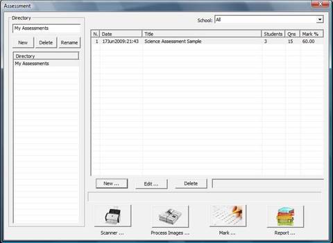
Figure 5.1: Main Assessment Module
5.1 Assessment Functions
5.1.1 Creating New
Assessments
a. Click on the “New …” button in the Assessment
Module (Figure 5.1)
b. A dialog box (Figure 5.2) is displayed
c. Select and enter the details of the assessment
d. Click on the “Create” button
5.1.2 Editing
Assessments
a. Click on the “Edit …” button in the Assessment
Module (Figure 5.1)
b. A dialog box (Figure 5.3) is displayed
c. Change the details of the assessment if needed
d. Select the student and view the scanned paper by
clicking on the “View Paper” button if necessary
e. Select the student and clear the scanned images
by clicking on the “Clear Data” button if needed
f. Click on the “Load Image” button to rescan the
student’s paper and a dialog box (Figure 5.7) is
displayed. Select the directory
containing the images of the student’s paper. Click the “OK” button
h. Click on the “Edit Questions …” button to
manually segment the images of the student. Please see
the
section on “Manually Editing Student’s Results” in the Chapter more details
i. Click on the “Exit” button
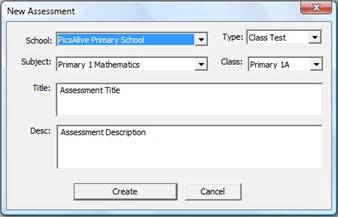
Figure 5.2: Creating a New
Assessment
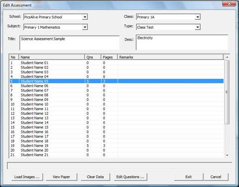
Figure 5.3: Editing the Assessment
5.1.3 Deleting
Assessments
a. Click on the “Delete” button in the Assessment
Module (Figure 5.1)
b. The assessment will be automatically deleted
5.2 Scanning Assessment Papers
It is important to note that image resolution must be at least 150x150
dpi (dots per inch). The recommended image
scanning resolution is 300x300 dpi. To
minimize file sizes and speed up the scanning process, the image mode should be
set to Black and White. SMART supports
nearly all scanners and imaging devices through the TWAIN (Technology Without
An Interesting Name) standard. TWAIN is
a standard software protocol and applications programming interface
(API) that regulates communication between software applications and imaging
devices such as scanners.
5.2.1 Scanning
Procedure
a. Click on the “Scanner …” button ![]() in the Assessment Module (Figure 5.1)
in the Assessment Module (Figure 5.1)
b. A dialog box (Figure 5.4) is displayed
c. Click on the “Select Scanner” button to choose
the scanner (Figure 5.5) and click on the “Select”
button
d. Select the Directory, file format and the check
box to overwrite image files. It is
recommended
that users use the default settings
shown in Figure 5.4. Note that the
scanned images will be
named sequentially (e.g. image0001.tif,
image0002.tif, image0003.tif and so on)
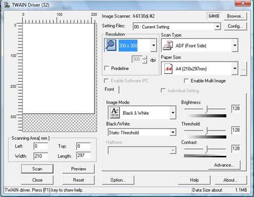
e. Click on the “Acquire Image …” button and the
scanner parameters dialog box is displayed (Figure
5.6(a) ). It is recommended that the
scanning resolution be set to 300x300 dpi and the image mode
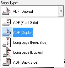
is set to “Black and White”. For double sided scanning, select the “ADF
(Duplex)“ option (see
Figure 5.6(b) ) from the Scan Type
option in Figure 5.6(a).
f. Click on the “Scan” button in Figure 5.6 to
start scanning. After scanning, click on
the “Close”
button
g. Click on the “Exit” button in Figure 5.4
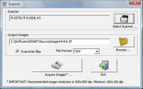
Figure 5.4: Scanner Module
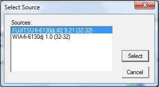
Figure 5.5: Selection of Scanner
(a)
(b)
Figure 5.6: Scanner Parameters (a)
Main Setup Menu (b) Double-Sided
Scanning
5.3 Data Processing of Images
If you have any questions or experience any difficulties in SMART,
please contact us at support@picsalive.com
and we will respond promptly
5.3.1 Extracting and
Automatic Marking of Questions
a. Click on the “Process Images …” button ![]() in the Assessment Module (Figure 5.1)
in the Assessment Module (Figure 5.1)
b. A dialog box (Figure 5.7) is displayed. Note: If there are existing students’ data in
the assessment,
a dialog
box will appear to select whether to delete or retain the existing data.
c. Change the Source Directory and file format if
necessary. It is recommended that users
use the
default settings shown in Figure 5.7. The number of images detected is also shown.
The image
filenames must correspond to the page
numbers e.g. Page 1 of the assessment paper must be
saved as image0001.tif, Page 2 must be
saved as image0002.tif etc. Note that
filenames of images
MUST be in sequential order (e.g.
image0001.tif, image0002.tif, … and so on). An error message is
displayed if the image resolution is
less than 150x150 dpi
d. Select the File Format of the images (i.e. TIFF
or JPEG formats)
e. Click on the “OK” button to start the extraction
and automatic marking of questions
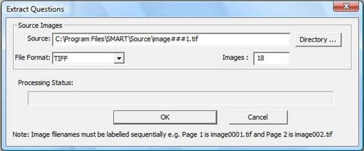
Figure 5.7: Process Images
5.4 Manual Editing of Student’s
Results
Users can manually overwrite the student and question data obtained
automatically from the SMART system.
5.4.1 Loading Student
Images
a. Click on the “Edit …” button in the Assessment
Module (Figure 5.1)
b. Select student ( see Figure 5.3)
c. Click on the “Load Images …” button and Figure
5.7 is displayed
d. Select the directory containing the scanned
images of the student’s paper using the “Directory …”
button.
Note that the number of images detected is shown
e. Click on the “OK” button. If the student’s Registration Number or the
Assessment ID detected in
the images differs from the selected
student and assessment, a warning message will be display.
Click on “Yes” in the warning message to
proceed. The student’s questions will be automatically
extracted from the images
5.4.2 Viewing Student
Images
a. Click on the “Edit …” button in the Assessment
Module (Figure 5.1)
b. Select student ( see Figure 5.3)
c. Click on the “Clear Data” button
5.4.3 Deleting Student
Data
a. Click on the “Edit …” button in the Assessment
Module (Figure 5.1)
b. Select student ( see Figure 5.3)
c. Click on the “Clear Data” button
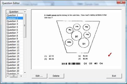
Figure 5.8: Main Assessment Module
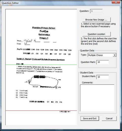
Figure 5.9: Main Assessment Module
5.4.4 Editing Student
Questions
a. Click on the “Edit …” button in the Assessment
Module (Figure 5.1)
b. A dialog box (Figure 5.3) is displayed
c. Click on the “Edit Question …” button and Figure
5.8 is displayed
d. Click on the “New …” button to insert a question
or “Edit …” button to make changes to the
question. Figure 5.9 is displayed. To insert a new image, use the “Browse New Image …” button.
To redefine the Start and End location
of the question in the image, click on the “Question
Location” button. The first click on the image defines the
start line (green) and the second click on
the image defines the end line of the
question. Question parameters like type,
question marks,
student marks and comments can also be
changed (Figure 5.9)
e. Select the question and delete it using the
“Delete” button if necessary
f. Click on “Save and Exit” button in Figure 5.9 to
save changes
5.5 Creating Reports
5.5.1 Procedure to
Generate Reports
a. Click on the “Report …” button ![]() in the Assessment Module (Figure 5.1)
in the Assessment Module (Figure 5.1)
b. A message (Figure 5.10) is displayed after the
report is successfully generated
Figure 5.10: Report Generated
5.6 Marking Module
In the Marking Module, all questions individually extracted and
presented to the user. All MCQ (Multiple
Choice Questions) and MR (Multiple Response) questions are automatically
marked. The Marking Module allows other
questions types to be manually marked by presenting individual questions to the
user and storing user data back into the question. To access the Marking Module, Select the
Assessment Module and click on the Marking Module icon. ![]()
Figure 5.11 shows the main user interface of the Marking Module. The
image is shown on the left hand side while the marking parameters are displayed
on the right side. The icons at the
bottom of Figure 5.11 are short-cuts to the functions of the Marking Modules. A list of functions denoted by the icons is
shown in Table 5.1.
Notice the Progress field of 66.67% at the top right corner of Figure
5.11. This indicates the percentage of
the questions already marked. A list of
the questions, students and classes are displayed on the right side of Figure
5.11. Note that the question type and
the correct answer are also detected by the system from the barcodes.
A useful feature of the Marking Module is to sort and mark the paper by
questions as shown Figure 5.12. Select
“Unmarked” from the List field and all unmarked questions will be
displayed. Next, select “Questions” from
the View field. Marking by questions
increases efficiency and marking productivity.
Comments can be added into the image by first typing into the comments
box. There are some pre-programmed
comments in the drop-down list. Insert
the comments into the image using the Insert Text icon ![]() . To view
the original image, click on the
. To view
the original image, click on the ![]() icon. Figure 5.13 shows the user interface to view
the original images.
icon. Figure 5.13 shows the user interface to view
the original images.
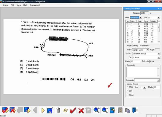
Figure 5.11: Extracted Question
Automatically Marked by System
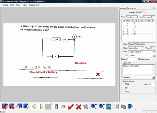
Figure 5.12: User Inserted
Comments
|
|
||
|
|
||
|
|
Save & Back |
|
|
|
Save & Next |
|
|
|
||
|
|
||
|
|
Save Data into Image |
|
|
|
Delete Image |
|
|
|
Clear All Data in Image |
|
|
|
Insert Tick |
|
|
|
Insert Cross |
|
|
|
Insert Text into Image |
|
|
|
Zoom In Into Image |
|
|
|
Zoom Out Into Image |
|
|
|
Rotate Image by 180 degrees |
|
|
|
Pre-assigned Settings and Marking Parameters |
|
|
|
View Original Image |
|
|
|
Exit Marking Module |
Table 5.1: Marking Module Icons
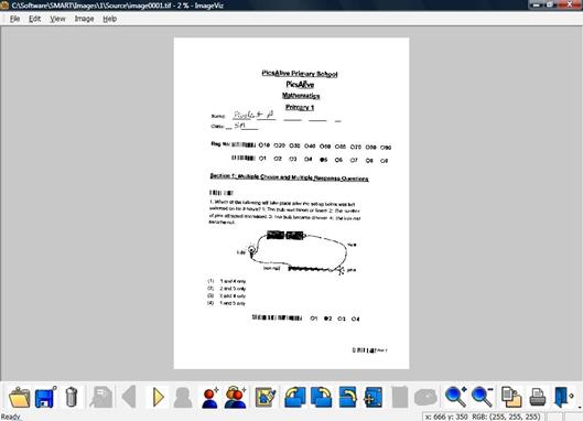
Figure 5.13: Original Image
5.7 Assessment Directory
Assessment can be organised into directories as shown on the left hand
side of Figure 5.1. Users can create, edit or delete directories. All directories create in the Assessment
Module will also appear in the Report Module.
Similarly, the report will also appear in the same directory as the
assessment.
5.7.1 Creating a New
Directory
a. Enter the name of the new directory in the text
box at top left of the Main Assessment Module as
shown in
Figure 5.1
b. Click on the “New” button. An error message will appear if there is
another directory with the
same name
5.7.2 Deleting a
Directory
a. Select the directory to be deleted from the left
of the Main Assessment Module (see Figure 5.1)
b. Ensure that all assessments in the directory is
removed.
c. Click on the “Delete” button
5.7.3 Renaming a
Directory
a. Select the directory to be renamed from the left
of the Main Assessment Module (see Figure 5.1)
b. The name of the directory will appear on the
text box. Edit and change the name of the directory
c. Click on the “Rename” button